
Pressure Transducer Working Principle: How Pressure Becomes a 4-20 mA Signal
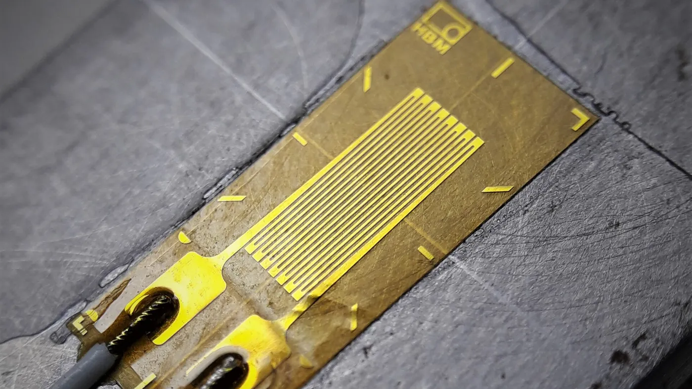
Table of Contents
Every industrial pressure transducer, regardless of brand or price, follows the same working principle: pressure acts on a diaphragm, the diaphragm deflects, a sensing element turns that deflection into an electrical change, and conditioning electronics convert it into a standard output such as 4-20 mA, 0-10 V or RS485. The details of step three — the sensing technology — are what separate one transducer from another. This guide walks through the full chain and explains the three most common sensing technologies.
The Working Principle in Five Steps
Trace the signal path from process media to your PLC and the principle becomes clear:
Pressure media
    │  (gas, liquid or steam pushes on the diaphragm)
    ▼
Diaphragm deflection
    │  (mechanical movement proportional to applied pressure)
    ▼
Sensing element
    │  (strain gauge, piezoresistive silicon or capacitive ceramic
    │   converts deflection into a resistance or capacitance change)
    ▼
Signal conditioning
    │  (amplification, linearization, temperature compensation)
    ▼
Standard output
    │  (4-20 mA two-wire, 0-10 V, 0-5 V or RS485/Modbus)
    ▼
PLC / display / SCADA reads pressure in bar, kPa or psi
The diaphragm is typically 316L stainless steel, ceramic or silicon, depending on media compatibility. Its deflection is tiny — fractions of a millimeter even at full scale — so the sensing element and electronics must be precise. That is why accuracy classes are quoted as a percentage of full scale (FS), such as ±0.25% FS.
Strain Gauge Sensing Elements
The strain gauge is the most widely used industrial sensing technology. A resistive pattern is bonded to, or deposited on, the diaphragm. When pressure deflects the diaphragm, the gauge stretches and its electrical resistance changes. The gauges are wired in a Wheatstone bridge configuration so that the tiny resistance change becomes a measurable voltage — typically in the range of 1-3 mV per volt of excitation.
Two variants dominate:
- Bonded foil gauges — a thin metal foil pattern glued to the diaphragm. Cost-effective, proven, and suited to general industrial duty such as hydraulics and pneumatics.
- Sputtered thin-film gauges — the resistive film is deposited directly onto the steel diaphragm in a vacuum process. Better long-term stability and lower drift, at a slightly higher cost.
Strain gauge transducers handle high pressure well — common ranges run to 600 bar and beyond — and tolerate vibration and shock better than some silicon designs. They are the default choice for hydraulic presses, injection molding machines and high-pressure test rigs.
Piezoresistive Silicon Sensing Elements
Piezoresistive transducers use a silicon chip with diffused resistors. When the diaphragm (often silicon itself, or a steel diaphragm coupled through oil) deforms, the mechanical stress changes the resistance of the diffused resistors far more strongly than in metal foil gauges. The result is a higher output signal and excellent sensitivity, which makes piezoresistive technology well suited to low-pressure ranges — from a few millibar up to tens of bar.
In media-isolated versions, a thin 316L diaphragm transfers pressure through a silicone oil fill to the silicon chip. This keeps aggressive media away from the chip while preserving sensitivity. Piezoresistive elements are also the basis of most miniature and OEM pressure transducers, where small size matters more than maximum robustness.
One trade-off to know: silicon elements are more sensitive to temperature than metal gauges, so good transducers include digital or analog temperature compensation. Check that the datasheet states a compensated temperature range — a typical figure is -20°C to +85°C.
Capacitive Ceramic Sensing Elements
Capacitive transducers measure pressure by changes in capacitance rather than resistance. A typical construction is an aluminum-oxide (Al₂O₃) ceramic cell: pressure deflects a ceramic diaphragm toward a fixed electrode, the gap shrinks, and capacitance increases. The electronics convert the capacitance change into a linear output.
The ceramic cell has two practical advantages. First, it is chemically inert, so it suits corrosive media, food processing and wastewater without special coatings. Second, many ceramic cells are "dry" — no oil fill — which removes a failure mode in applications where a ruptured diaphragm would contaminate the process. Accuracy is typically in the ±0.2% to ±0.5% FS class, which is adequate for most monitoring duties.
Sensing Technology Comparison
| Technology | How it senses | Typical accuracy | Strengths | Common ranges |
|---|---|---|---|---|
| Strain gauge (bonded foil / thin-film) | Resistance change of a bonded or sputtered gauge | ±0.1% to ±0.5% FS | High pressure, vibration, low drift (thin-film) | Up to 600 bar and above |
| Piezoresistive silicon | Resistance change of diffused silicon resistors | ±0.1% to ±0.25% FS | High sensitivity, low ranges, miniature sizes | Millibar to tens of bar |
| Capacitive ceramic | Capacitance change of a deflecting ceramic diaphragm | ±0.2% to ±0.5% FS | Corrosive media, dry cell, hygiene duty | Millibar to ~100 bar |
For a wider view of technologies including resonant sensors, see our pressure sensor types guide.
Signal Conditioning: From Millivolts to 4-20 mA
The raw sensing element output is far too small for a PLC to read directly. A raw strain gauge bridge might output a few millivolts at full scale, with nonlinearity and temperature effects on top. Signal conditioning electronics turn that into a clean, standardized signal:
- Amplification — boosts the millivolt bridge output to a usable level.
- Linearization — corrects the small nonlinearity between pressure and output.
- Temperature compensation — corrects zero and span drift across the compensated range.
- Output conversion — drives the final stage: a 4-20 mA current loop, a 0-10 V voltage output, or an RS485/Modbus digital interface.
| Signal stage | Typical level | Notes |
|---|---|---|
| Raw sensing element | 1-3 mV/V (strain gauge) | Needs amplification; affected by temperature |
| After conditioning | 4-20 mA / 0-10 V / RS485 | Linear, temperature-compensated, ready for PLC input |
The conditioning quality is what separates a ±0.5% FS instrument from a ±0.1% FS one. If you are wiring the output side yourself, our 4-20 mA guide covers loop wiring, scaling and troubleshooting in detail.
Frequently Asked Questions
What is the difference between a pressure transducer and a pressure sensor?
A sensor is the raw sensing element — diaphragm plus strain gauge, ceramic cell or silicon chip. A transducer adds signal conditioning and a standard output, so it is ready to wire to a PLC. The working principle described here covers the full transducer chain.
Which sensing technology is most common in industrial transducers?
Strain gauge technology is the most widespread for general industrial duty, especially hydraulics and high-pressure applications. Piezoresistive silicon dominates low-range and miniature designs, and capacitive ceramic is common where media is corrosive or hygienic.
How does a 4-20 mA transducer get its power?
Two-wire 4-20 mA transducers are loop-powered: the same two wires carry both the supply current from a 24 VDC source and the signal current. There is no separate power wire, which simplifies wiring on machines and plants.
Why does temperature compensation matter?
Sensing elements drift with temperature — zero and span move as the process or ambient temperature changes. Compensation electronics correct this across a stated temperature range, typically -20°C to +85°C for standard industrial models, so the output stays accurate in real plant conditions.
Conclusion
The pressure transducer working principle is a chain: diaphragm deflection, a sensing element that turns deflection into an electrical change, and conditioning electronics that output a standard signal. Once you understand which sensing technology sits in the middle — strain gauge, piezoresistive silicon or capacitive ceramic — you can match a transducer to your media, range and accuracy needs with confidence.
PRESSUREPOINT manufactures industrial pressure transducers across all three technologies, with 316L wetted parts, ranges from -1 bar vacuum to 600 bar, outputs of 4-20 mA, 0-10 V and RS485, and CE marking as standard. If you are specifying a transducer for a new machine or replacing an existing unit, send us your media, working pressure and connection — our engineers will confirm a suitable model quickly.
NEXT STEP
Ready to Spec the Right Pressure Transducer?
Send us your requirements — our team responds within 24 hours with pricing and lead time.
Written by
PRESSUREPOINT TeamPressure instrumentation specialist. PRESSUREPOINT helps engineers and maintenance teams source factory-direct pressure transducers and transmitters.